Electrical Engineering Student (4th Year - Grad: June 2020)
| QR Code Reader | |
|---|---|
|
| |
| Date | May 2019 |
| Language | C++ |
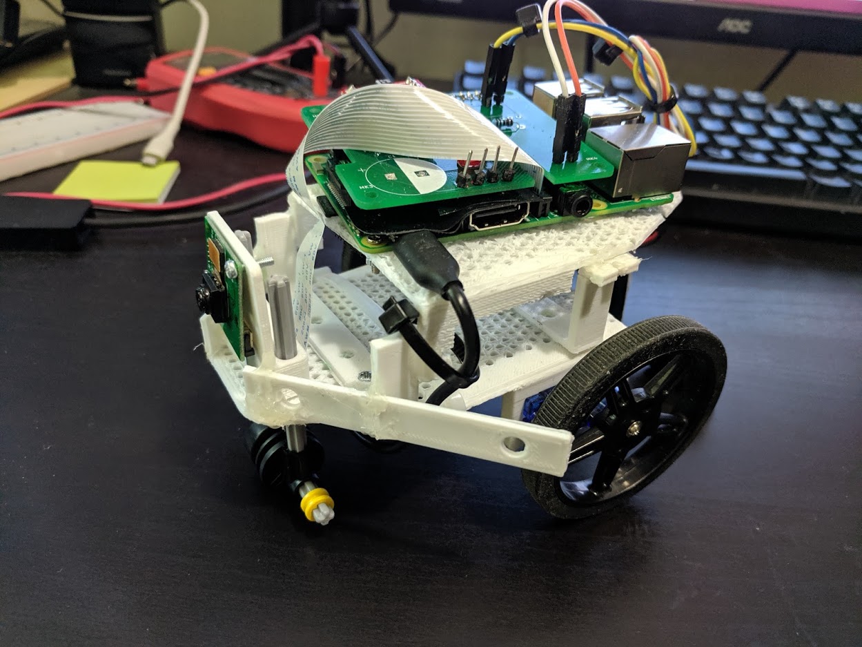
| Board | Raspberry Pi 3B+ |
| Program | Visual Studio 2017, SolidWorks, KiCAD |
| Peripherals | Pi Camera, Ultrasonic Sensor, Motor Driver |
| Github | Maze Robot |
The maze robot is built to navigate through a maze by sensing coloured markers to turn. Markers are placed at corners with blue indicating a right and red indicating a left.
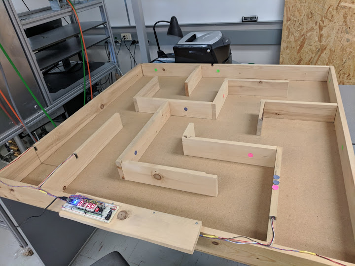
The algorithm is written in C++ on the Raspberry Pi. First, it thresholds the image to isolate only the desired colours, red or blue. Afterwards, it fits a circle on the colours to see if they are a valid marker and not noise. After it detects the colour, it waits for the ultrasonic sensor to report that the robot is 7 cm from the wall. From there, it will stop and turn appropriately.
The motors are controlled via an H-Bridge motor controller. It allows for control of two motors independently with speed capabilities.
The PCB is designed in KiCAD and sent to AllPCB to be manufactured for the project.
The chassis is 3D printed and designed in SolidWorks.